Tip #1: Highlight Connectors
To highlight the connectors, select an element in a diagram (workspace) and press “L” (keyboard) to highlight its incoming and outgoing flows. Incoming flows will be highlighted in Red and Outgoing in Green.

Figure 1 Highlight Connectors
Tip #2: Insert Existing Element
Draw connector to an existing model Element. One can insert an existing model element and establish a relationship while drawing a new connector Follow usual steps to draw a connector, but press “Shift” before choosing the type of element to be created, this will invoke the “Select Existing Element” dialog to choose a model element instead of creating a new element.
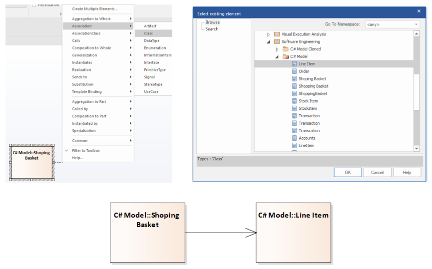
Figure 2 Insert Existing Element
Tip #3: Bend Connectors
Press “Shift” introduces a bend point while drawing a connector, enabling to draw a custom style connector.
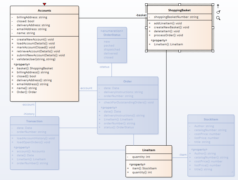
Figure 3 Bend Connectors
Tip #4: Generate Report from Diagram
Generate a report on elements in a diagram, switch to “List View”(Right-click on Diagram and select open in diagram🡪List View), select the elements and use the “Rich Text Report” button.
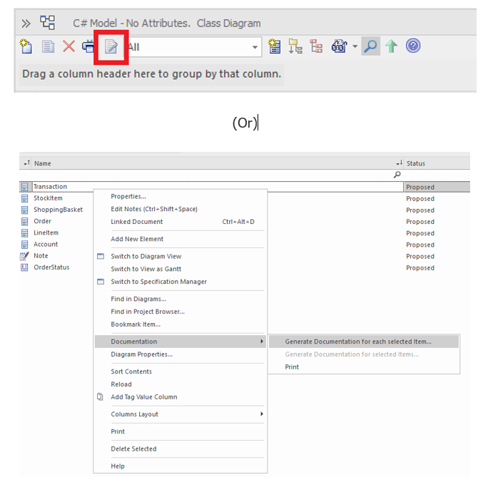
Figure 4 Generate Report from Diagram
Tip #5: Bookmark Elements
Select Element(s) and use “Shift” + “Space” to add bookmark. Bookmarked elements can then be retrieved in Model Search (Ctrl + F | Diagram Searches | Find Bookmarked Elements) and also be generated as RTF report.
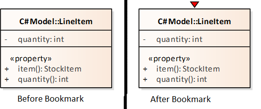
Figure 5 Bookmark Elements
Tip #6: Set Default Toolbox
Pin your favorite toolboxes using “More Tools -> Set Toolbox Visibility”. This enables the desired toolbox visible in all diagram pages.

Tip #7: Bezier Style Connector
Create a Bezier Style Connector by adding a tagged value (_Bezier = 1).

Figure 7 Bezier Style Connector
Tip #8: Document with Pre-defined settings
Creating a resource document lets you to Auto Generate documents with pre-defined settings.
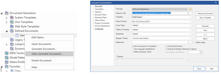
Figure 8 Document with Pre-defined settings
Tip #9: Update Elements Status
Update the status of all elements in a package and its child packages using ” Design | Edit | Advanced | Update Status”.
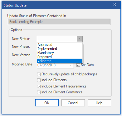
Figure 9 Update Elements Status
Tip #10: Favorites Folder
Create a favorites folder in the “Model Views” to quickly access your frequently used items.
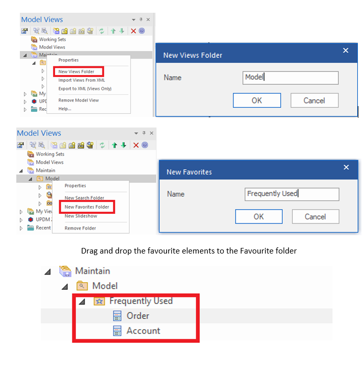
Tip #11: Diagrams Slideshow
Create a Slideshow folder in the “Model Views” to run screen-based presentations of a set of diagrams.
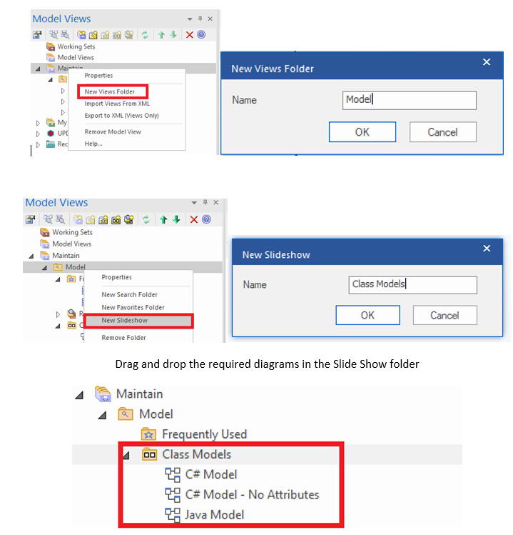
Tip #12: Move elements along its axis
Select element and press “Shift” to move the element along its axis.
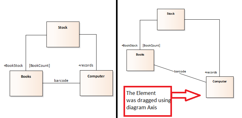
Figure 12 Move elements along its axis
Tip #13: Create Realization Relationship
Move an internal requirement (Element Properties Window | Requirements Tab) over any diagram element to implicitly create a realization relationship.
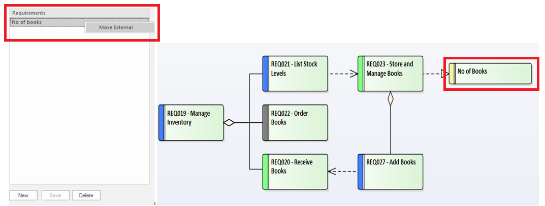
Figure 13 Create Realization Relationship
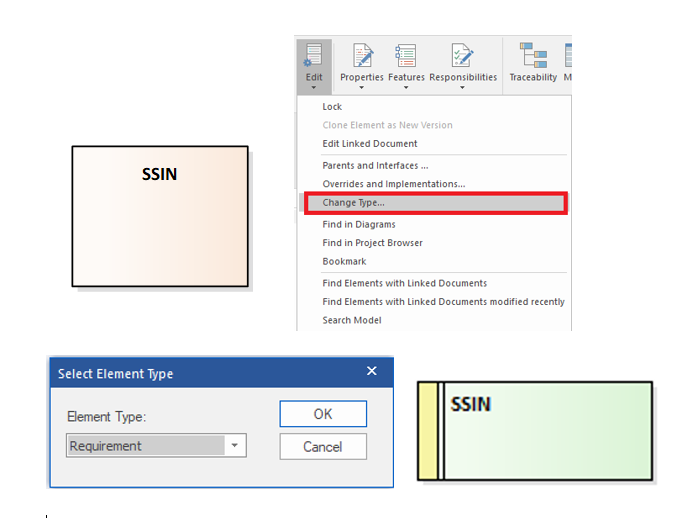
Tip #14: Change Element Type
Change type of an element. Select an element “Design | Element | Change Type”.
Tip #15: Project Template Package
Add elements to a Package and configure it as Template package (Configure | Project Template Package | Select the Template Package) to create new elements based on a template package.
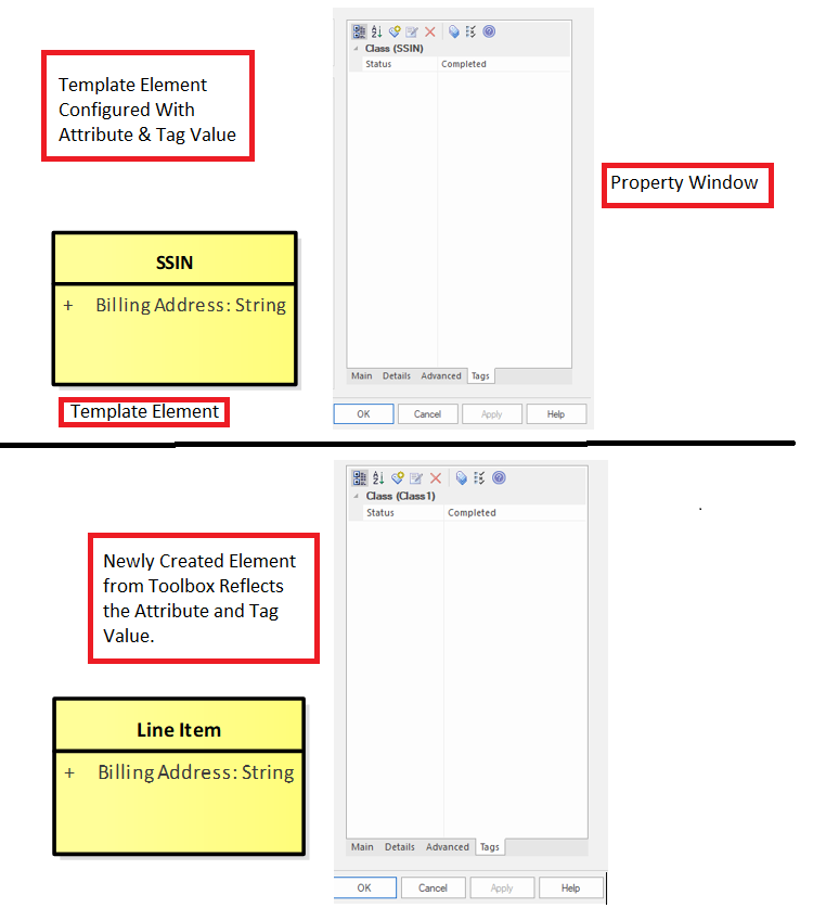
Figure 15 Project Template Package
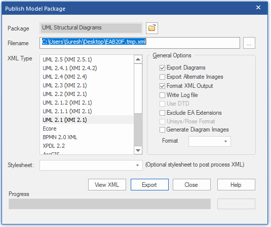
Tip #16: Project Publish
Use “Publish |Technologies |Publish” to export a model in various XML formats.
Tip #17: Filter Element Type on Diagram
Use “Layout | Edit | Select Elements by Type” to filter element by type and stereotype on a diagram.
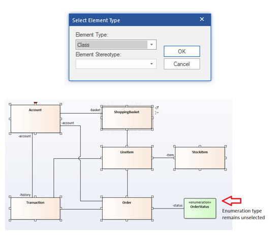
Figure 17 Filter Element Type on Diagram
Tip #18: Auto Names and Counters
Use “Auto Names and Counters” from Settings menu, to configure naming and numbering convention for elements.
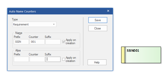
Figure 18 Auto Names and Counters
Tip #19: Show / Hide connectors
“Links” tab in Element Properties window can be used to Show / Hide a relationship in the diagrams.
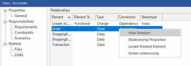
Figure 19 Show / Hide connectors
Tip #20: Export Diagrams to RTF Document
Generate a Diagrams Only report from Model using the “Export Diagrams to RTF Document” dialog (Ctrl + Shift + F8).
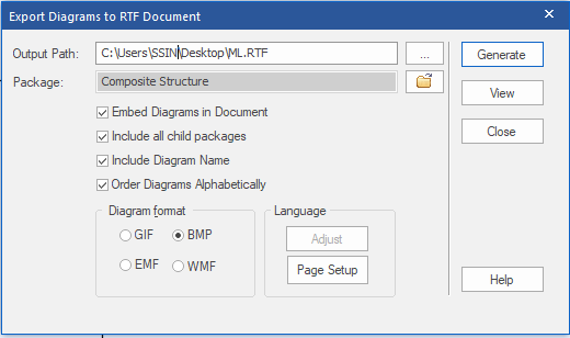
Figure 20 Export Diagrams to RTF Document
Tip #21: Stereotyped Nodes with Icons
Adorn your deployment diagrams with pre-defined stereotypes for Nodes. Use pc, pc client, pc server, server, storage, etc. to add custom icons

Figure 21 Stereotyped Nodes with Icons
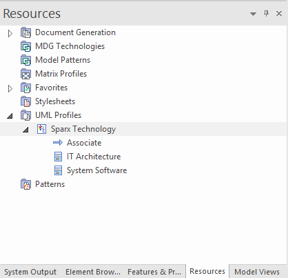
Tip #22: UML Profiles
Save custom stereotypes with tagged values as profile items and import into Resources->UML Profiles to simplify modeling.
Tip #23: Synchronize tagged values
Synchronize your tagged values associated with stereotypes using the “Synch Tagged Values and Constraints” option by right clicking the intended element in the toolbox.

Figure 23 Synchronize tagged values
Tip #24: Convert Linked Element
Create a local copy of a referenced element in a diagram by using “Convert Linked Element to Local Copy” option in diagram context menu (Advanced). This will not maintain any relationship with existing elements.
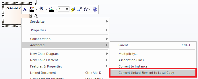
Figure 24 Convert Linked Element
Tip #25: Find in Diagrams
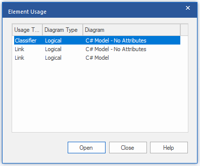
Use Find in Diagrams (Ctrl + U) from project browser to find the Link and classifier instances of an element in all diagrams.
Tip #26: Shortcuts for Tasks
Use “Shortcuts” menu item from “Learning Center” to begin Enterprise Architect tasks appropriate to the topic.
Tip #27: Incorporate Model Templates
Incorporate Model Templates in MDG Technology by following the guidelines
https://www.sparxsystems.in/blogs/import-model-patterns-into-enterprise-architect-through-add-in/
Tip #28: Project Calendar
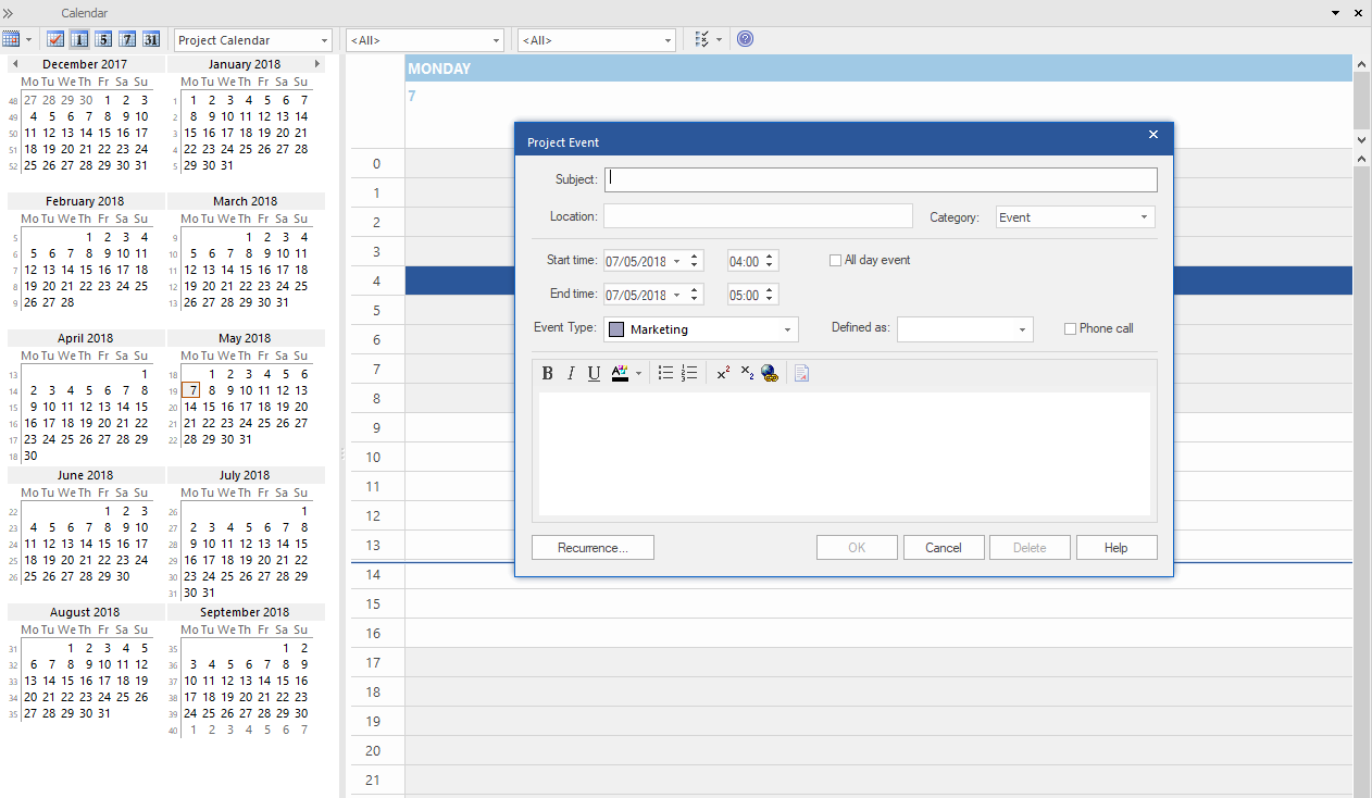
Use Start | Collaborate | Calender to Add Events, Meetings and Milestones.
Tip #29: Linked Note
Create individual “Linked Note” for an attribute and for an operation of a class element. Select attribute/operation and right-click from context menu choose Create Linked Note.
Tip #30: Set Visible Relationships
To Show/Hide the connectors in a diagram use “Layout | Diagram | Appearance | Set Visible Relationships” or “Ctrl + Shift + I”

Figure 28 Set Visible Relationships
Tip #31: Exclude images from RTF document
Use Diagram | Properties “Exclude image from RTF documents” to exclude the diagram images from any RTF document generated on the parent package or element.
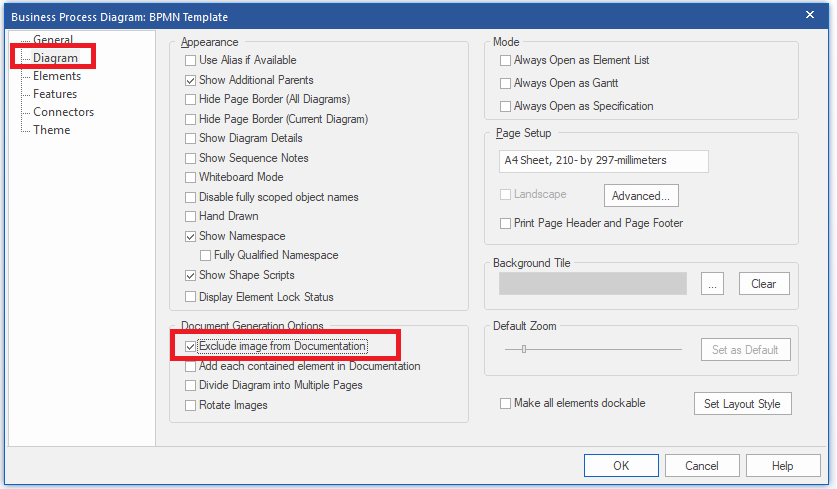
Figure 29 Exclude Image for RTF Document
Tip #32: Context Filter
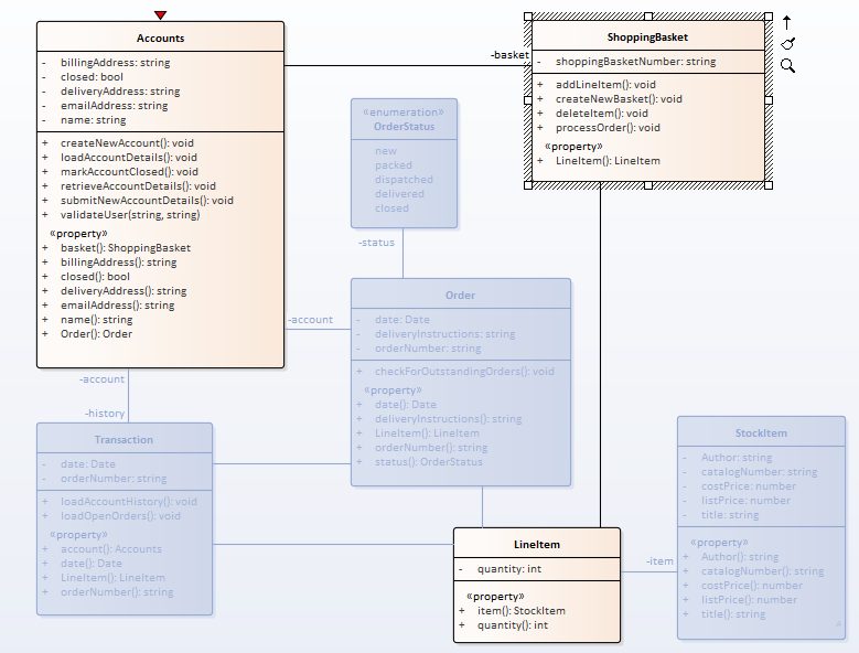
Use Context Filter (Layout | Filter | Relationships) to play up the elements on the diagram that are directly related to the selected element. This one is very useful in complex diagrams.
Tip #33: Set Direction for Association
Use “Association default = source –> target” (Tools | Options | Links) to automatically set the direction of new Associations, flowing from source to target element.
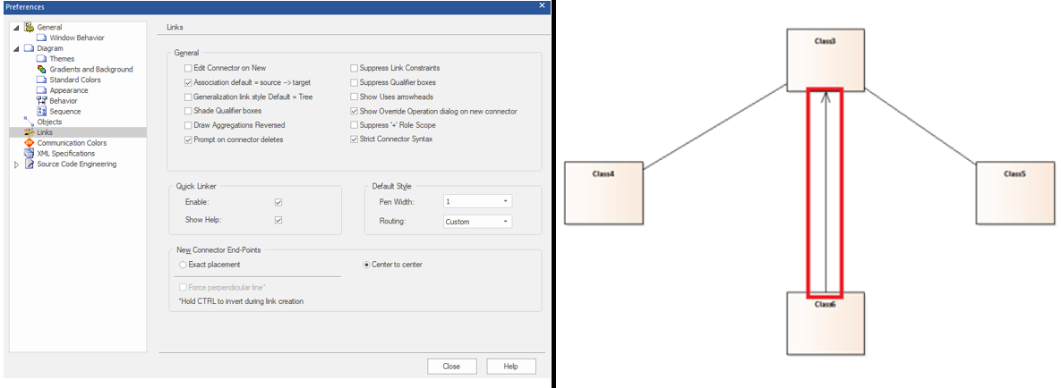
Figure 31 Set Direction for Association
Tip #34: Change Element Default Color
Use Element | Appearance | Default Appearance (F4), to change an element color on all diagrams except diagrams that override the appearance or use the format painter in the diagram toolbar to apply only on the current diagram.
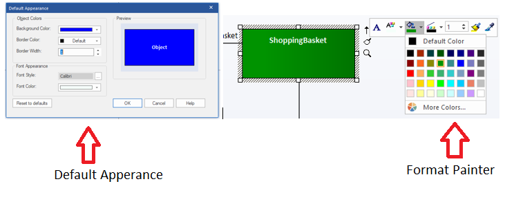
Figure 32 Change Element Default Color
Tip #35: Export Tagged Values
Use Configure | Model | Transfer | Export Reference Data and select “Tag Value Types” from “UML Types” to export all the custom “Tagged Values” in the model.
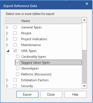
Figure 33 Export Tagged Values
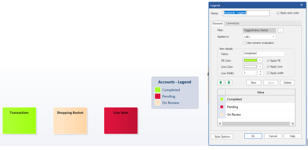
Tip #36: Diagram Legend
Use “Diagram Legend” to assist in distinguishing different elements, connectors or systems in a diagram.
Tip #37: EA Command
Use Hyperlink of type “EA Command” to select and perform list of Enterprise Architect commands.

Tip #38: Execute a script
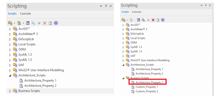
To execute a script, press Ctrl while you double-click on the script name.
Tip #39: Copy Script
To copy Script, select Script and drag and drop pressing Ctrl to create a copy of the script into the new user scripts folder.
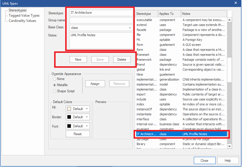
Tip #40: Add Stereotypes
Configure | UML Types | Stereotype, to Add, Modify or Delete stereotypes.
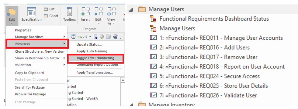
Tip #41: Level Numbering
Use Design | Package | Edit | Advanced Toggle Level Numbering to display level numbering of elements of selected package in the project browser/list view.
Tip #42: Code Samples
Refer Code Samples to handle enterprise architect repository using external projects from “C:\Program Files (x86)\Sparx Systems\EA\Code Samples”.
Tip #43: Code Gen default Language
Set default Language for Code Generation using “Configure | Options “.
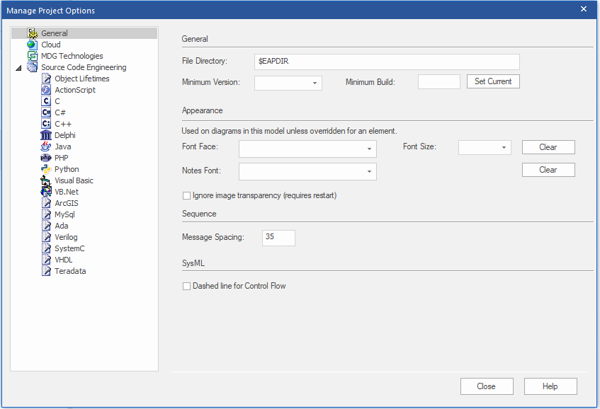
Figure 39 Code Gen default Language
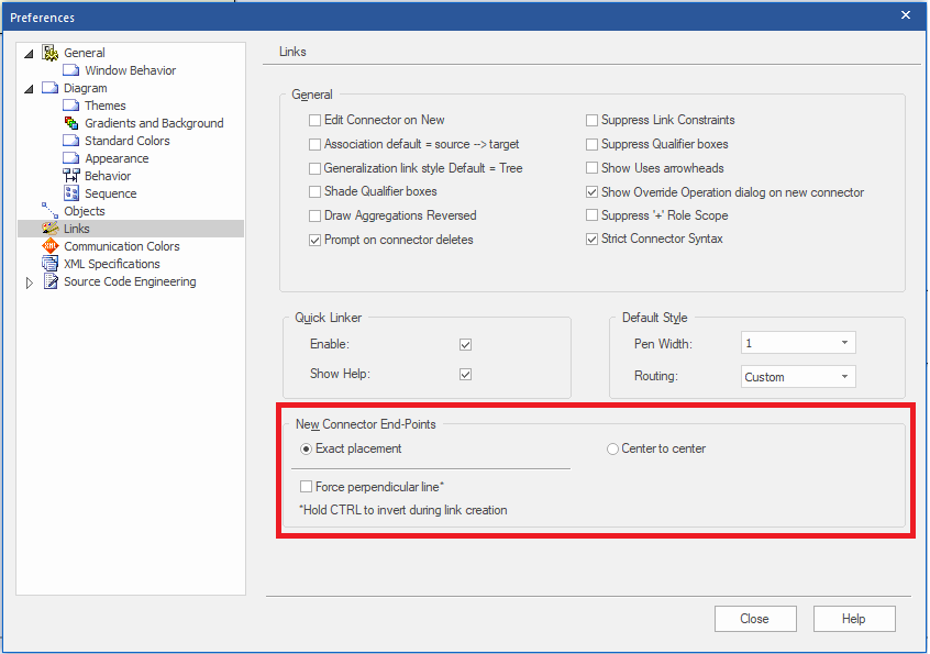
Tip #44: Exact Placement
Use “Exact Placement” option from Tools->Options->Links to set the orientation of the new connectors to the exact point in the target element.
Tip #45: Duplicate Element Properties
Use the “Element Browser” to copy element features from one element to another.
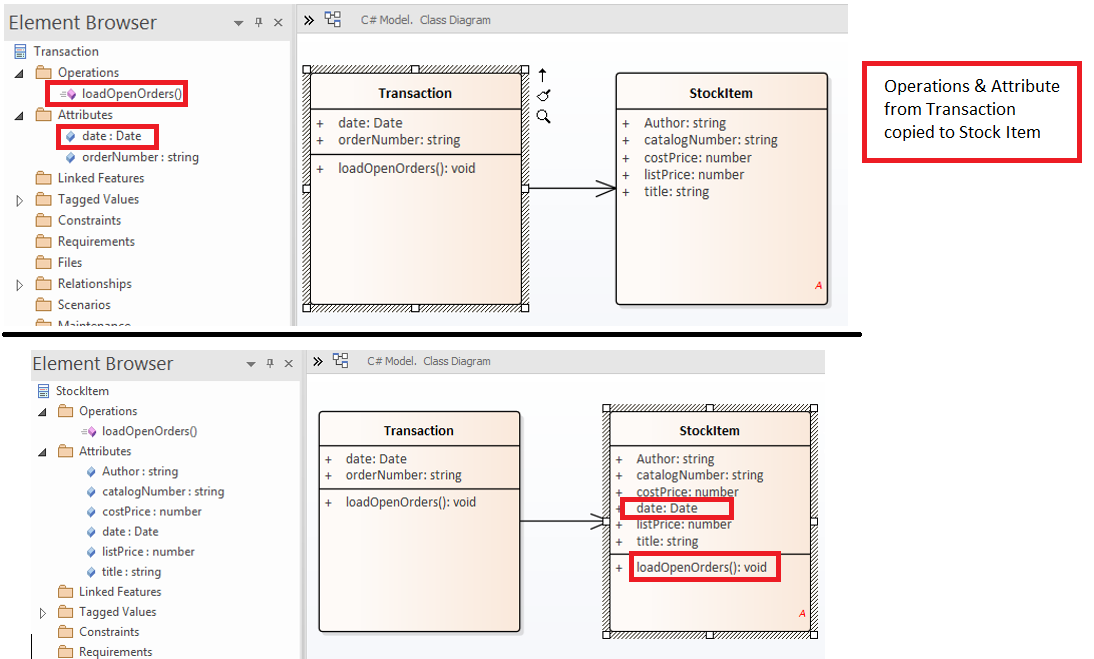
Figure 41 Duplicate Elements Properties
Tip #46: Model Default Diagram
Open a diagram choose “Layout | Diagram | Manage | Set as Model Default” to display it when you open the model.
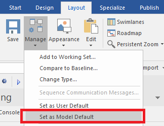
Figure 42 Model Default Diagram
Tip #47: User Default Diagram
Set a diagram as the User default from “Layout | Diagram | Manage | Set as User Default” to display the diagram, when the user opens the model.
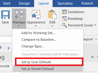
Figure 43 User Default Diagram
Tip #48: Add Tagged Value to Elements
Add the same tagged value to multiple elements. Select Multiple Element | Right Click | Add Tag Values.

Figure 44 Add Tagged Value to Elements
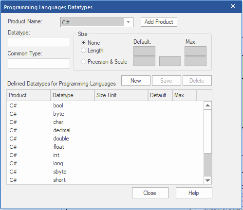
Tip #49: Extend Data Types
Extend the set of inbuilt data types for a standard programming language from Code | Options | Configure Code Engineering Datatypes.
Tip #50: Display Diagram Property
Add Diagram Details in the Diagram. Open Diagram Properties window(Double – click on Diagram workspace) | Diagram Tab | click on checkbox Show Diagram Details
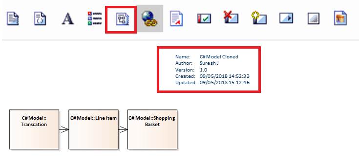
Figure Display Diagram Property
Tip #51: Add Macro Definition
Add New Macro definition to a language. “Setting | Preprocessor Macros”.
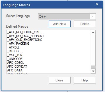
Figure 47 Add Macro Definition
Tip #52: QA Reports & Metrics
Use “QA Reports & Metrics” to monitor and report, on the outstanding details on a package.
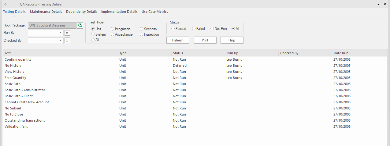
Figure 48 QA Reports & Metrics
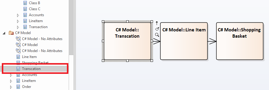
Tip #53: Locate Element
Locate the diagram object in the Project Browser using “ALT+G”.
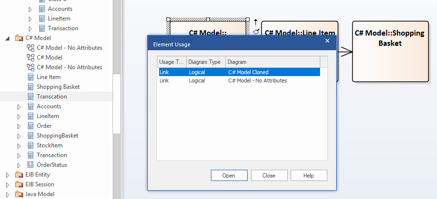
Tip #54: Element Usage
Find the element usage by selecting an element in “Project Browser” then press “CTRL + U”.
Tip #55: Find Orphan Elements
Find elements that are not used in any diagrams. Press Ctrl + F | Diagram Searches | Find Orphans.

Figure 51 Find Orphan Elements
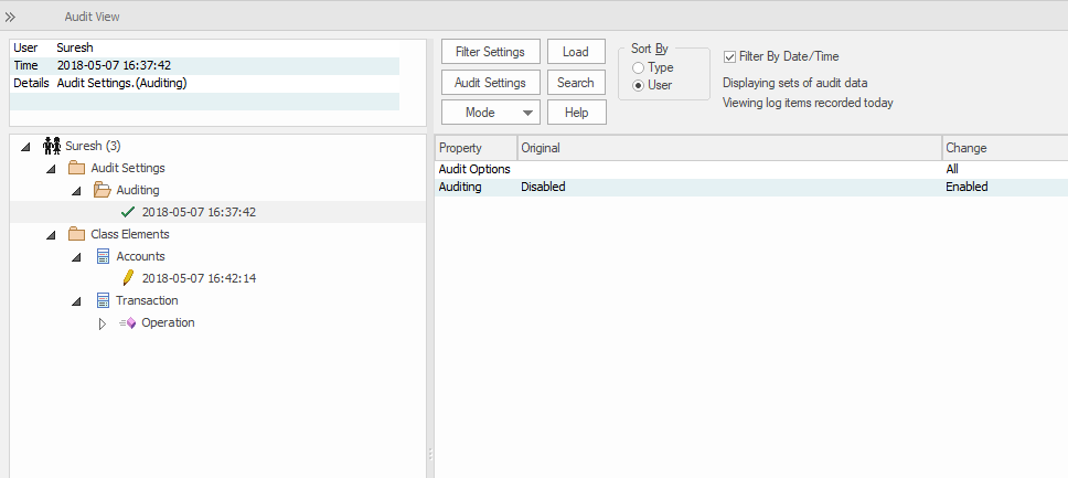
Tip #56: Audit History
Use “Configure | Auditing” to audit all the modifications in entire project. Audit view could be sort by Type & User.
Tip #57: Place Related Elements
Place the related elements of an element in the diagram using “Traceability” (Start | Trace) window Right Click on an element. Place element on the Diagram.

Figure 53 Placed Related Elements
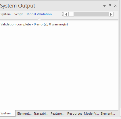
Tip #58: Validate Project
Use “Design | Package | Edit | Validation | Validate Current Package ” to validate model against known UML rules.
Tip #59: Create Shape Scripts
Use “Configure | Reference Data | UML Types” to apply Shape scripts to custom stereotypes.
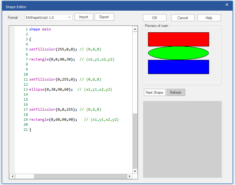
Figure 55 Create Shape Scripts
Tip #60: Instant Toolbox
Use “Shift and Right-Click” or space bar on diagram workspace to get the toolbox instantly.
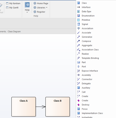
Tip #61: Create Multiple Elements
“Hold Ctrl and Right-Click” on the diagram workspace then select “Create Multiple Elements” to add multiple elements. Change the type of element from type drop-down.
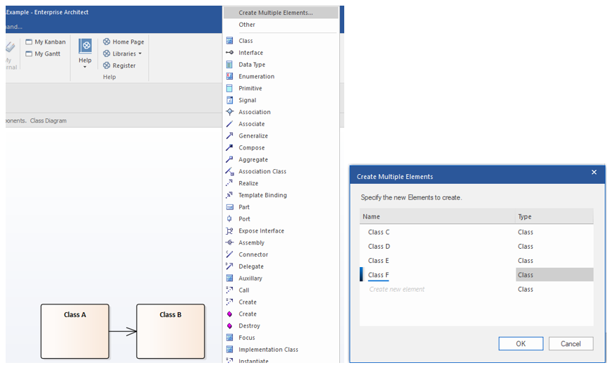
Figure 57 Create Multiple Elements
Tip #62: Import Elements from Clipboard
Import names from clipboard by “hold Ctrl and Right-Click” on diagram workspace then select “Create Multiple Elements”. Right click on the blank space. Then click “Import Names from Clipboard”.
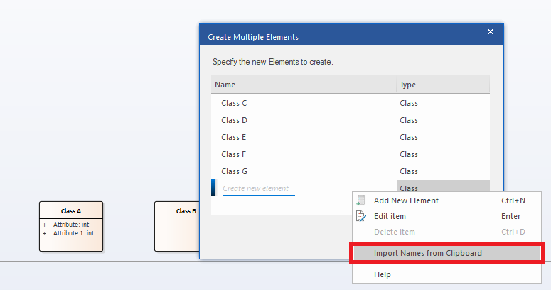
Figure 58 Import Elements from Clipboard
Tip #63: Repeat Element
To repeat the last created element type use “Ctrl + Click.”
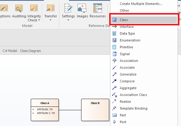
Tip #64: Repeat Connecter
Use F3 to repeat the last created connector type.

Tip #65: Draw Elements without Toolbar
Draw elements without toolbar by simply using “ctrl +shift +arrow keys”.
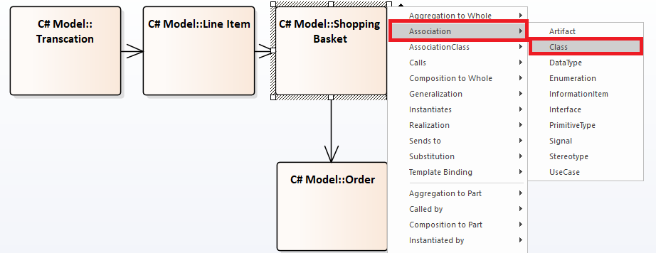
Figure 61 Draw Elements without Toolbar
Tip #66: Add New View/Package
Use “Ctrl + w” to add a new view or package to a currently selected model root view or package.
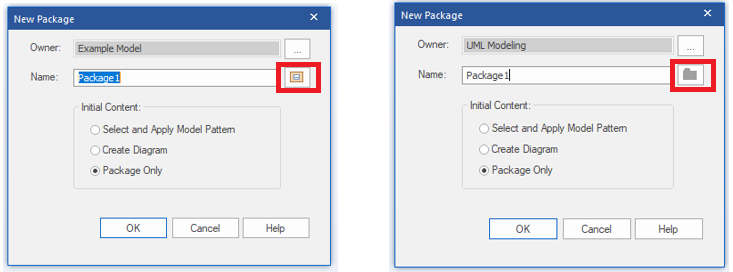
Figure 62 Add New View/Package
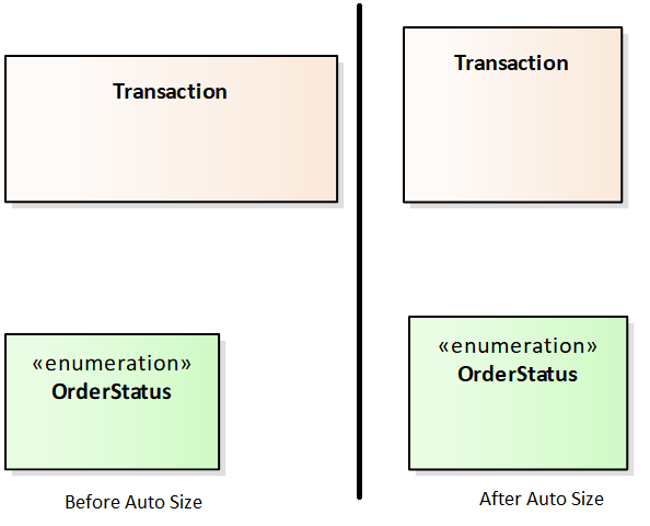
Tip #67: Auto Size Elements
Auto size (Alt + z) resizes objects to best fit. This can be quite handy when you enable / disable Element’s Features (Feature Visibility).
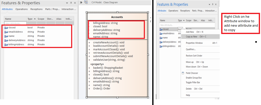
Tip #68: Attributes Window
Use Features & Properties window to Add/Edit/Delete Attribute. Select the element and Press “F9” to open up attributes tab in features window.
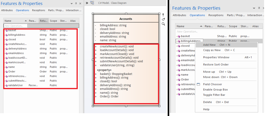
Tip #69: Operations Window
Use Features & Properties window to Add/Edit/Delete Operation. Select the element and Press “F10” to open up operations tab in features window.
Tip #70: Generate Excel Report from Query
Generate CSV report with from query results. Use Ctrl+F | Run a Search. Export results using CSV Import/Export Option
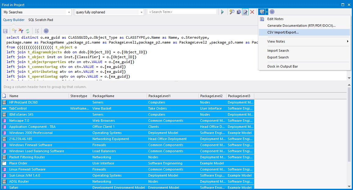
Figure 66 Generating Excel Report from Query
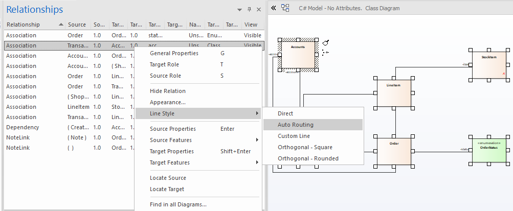
Tip #71: Change Line Style
Change line styles for multiple connectors at a time using “Relationships Window”. Select a few objects in the diagram, see all its connectors in the relationship window -> Right click -> Lines Style -> Choose desired line style.
Tip #72: Apply Line Style
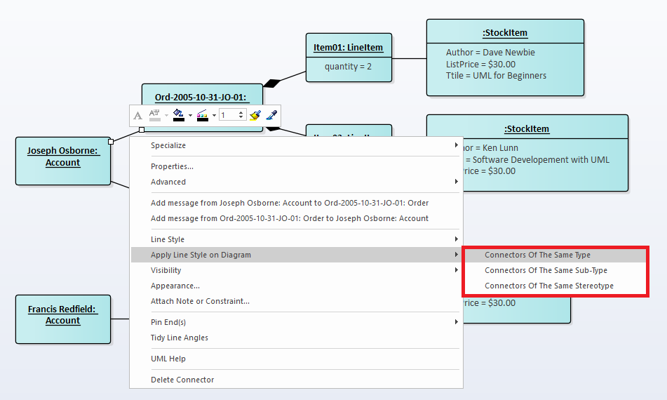
Use “Apply Line Style to -> All connectors of same type / stereotype” to quickly apply line styles to multiple connectors in a diagram.
Tip #73: Switch Between Windows
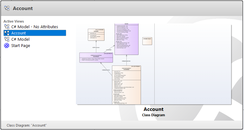
Use “Ctrl + Tab” to switch between open windows within Enterprise Architect. One of the less known, highly useful feature to flip between item diagrams.
Tip #74: Instant Copy
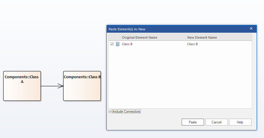
Select an object in diagram, hold ctrl and drag to a new position to create object as new (copy)
Tip #75: Add Attributes Inline
Add attributes in line with “Ctrl + Shift + F9” – one of the most commonly used trick in Class models.
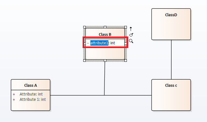
Figure 71 Add Attributes Inline
Tip #76: Add Operations Inline
Add operations in line with “Ctrl + Shift + F10” – one of the most commonly used trick in Class models.
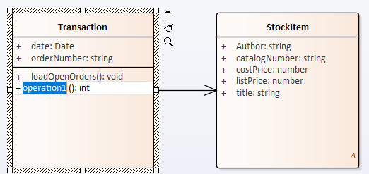
Figure 72 Add Operations Inline
Tip #77: Use Diagram Compare
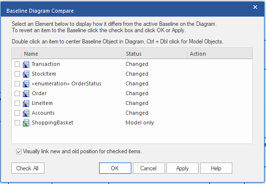
Use Diagram Compare (Layout | Diagram | Manage | Compare to baseline) option to compare your diagrams to previous state. Handy feature to keep track of diagram changes.
Tip #78: Diagram Frame
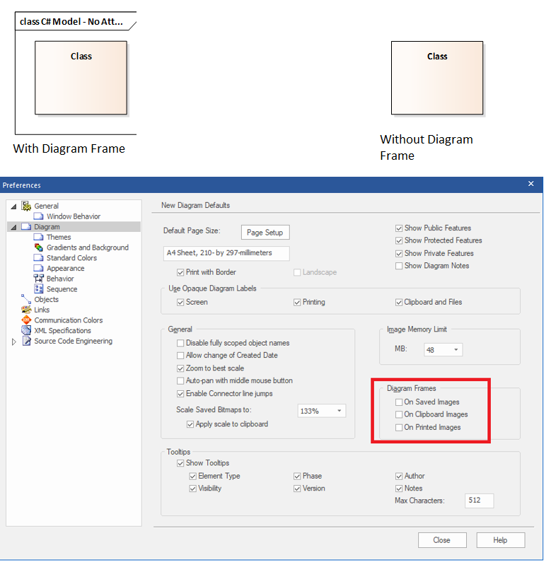
Configure “Diagram Frame” (Start | Preferences | Diagram Tab) to copy images with/without diagram frames.
Tip #79: Image Memory Limit Property
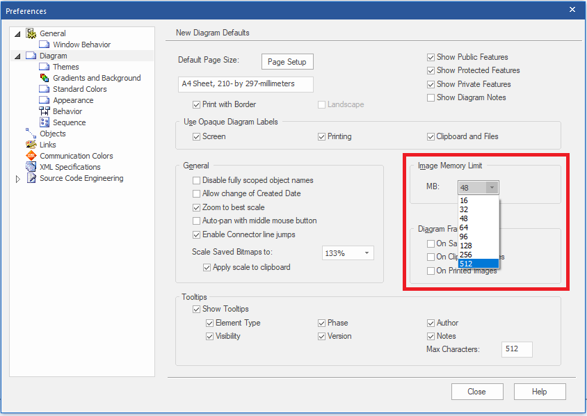
Increase the Image Memory Limit (Start | Preferences | Diagram Tab) property to get better quality images in HTML / Clipboard
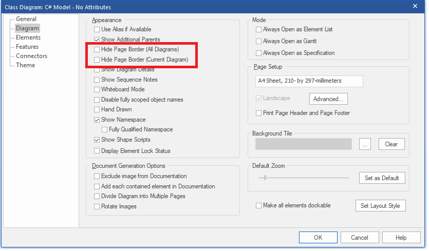
Tip #80: Hide Page Border
Use “Start | Preferences | Diagram Tab” to Show/Hide page border of the diagrams.
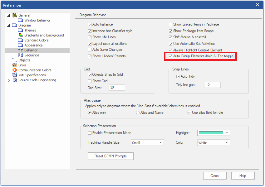
Tip #81: Auto Group Elements
Use “Start | Preferences | Diagram | Behavior | Auto Group Elements” to set grouping elements as default behavior in all the diagrams.
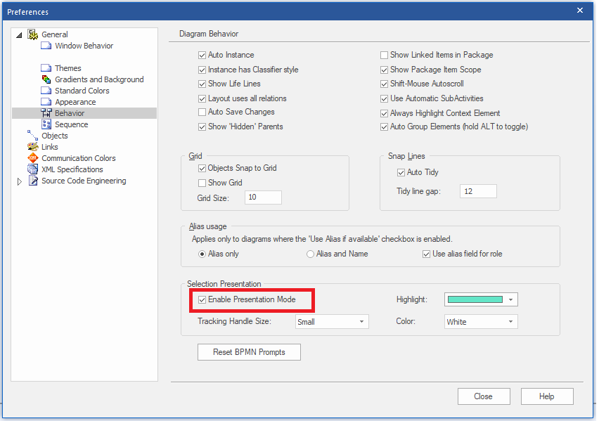
Tip #82: Presentation Mode
Enable “Presentation Mode” to hide popups / on-hover messages, etc. (Start | Preferences | Diagram | Behavior)
Tip #83: Show Direction
Use “Show Direction” (Layout | Helpers | Show Direction) to highlight incoming and outgoing relationships of selected element

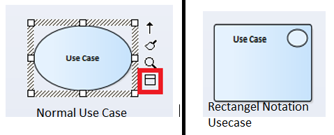
Tip #84: Rectangle Notation
Change Element Appearance using “Use Rectangle Notation” icon below quick linker
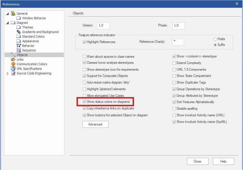
Tip #85: Show Status Colors
Display element status on diagrams using “Show Status Colors” (Start | Preferences | Diagram | Objects).
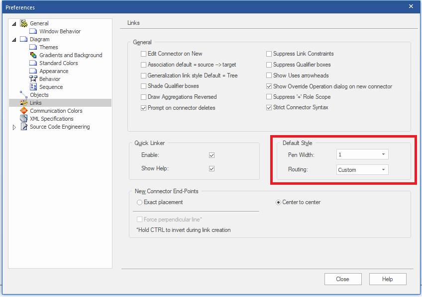
Tip #86: Set Line Style/Width
Use “Pen Width”, “Routing” options (Start | Preferences | Links) to set line style / line width across all diagrams
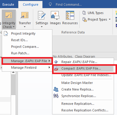
Tip #87: Compact EAP
In EAP projects, doing a Compact .EAP File (Configure | Integrity Check | Manage .EAPX/.EAP File | Compact .EAPX/.EAP File) on a regular basis helps to reduce the size of file in large models.
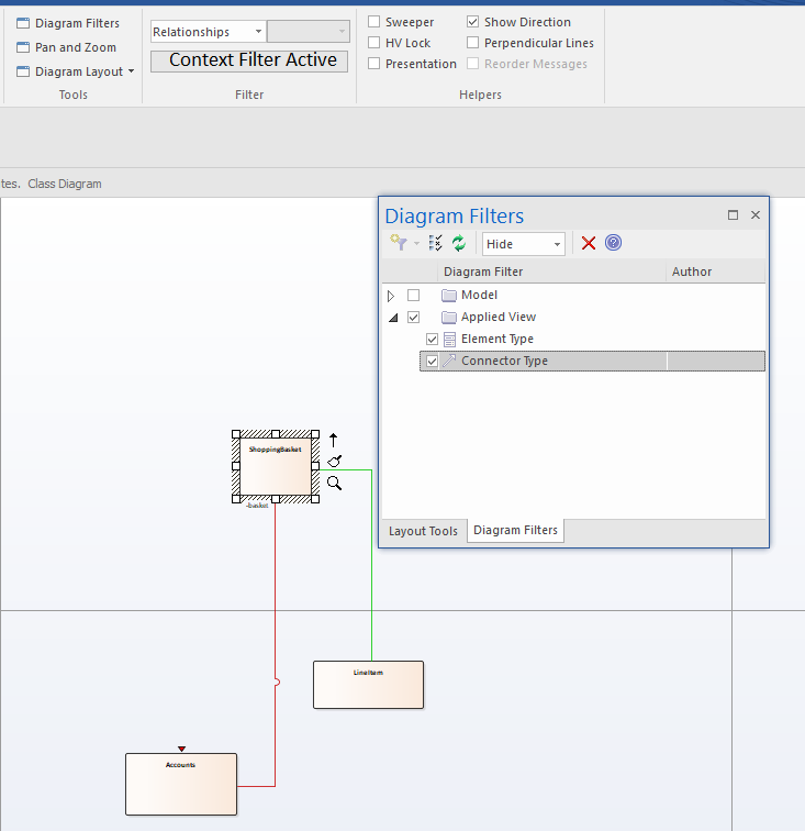
Tip #88: Diagram Filters
Use Diagram Filters, and set mode to “Hide” this will allow normal “Context Filtering” to hide non-context items (Default behavior is greying out)
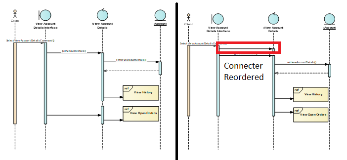
Tip #89: Reorder Messages
Hold “Alt” and move messages to reorder messages in Sequence Diagrams.
Tip #90: Recently Modified Elements
Set Auto notifications on new items in the model by using “Recently Modified Elements” Search in “Model Views” and setting auto-refresh. To identify the recently modified elements, create a “New Search folder” under “View Folder” in Model Views. To check the Recently modified elements (Start | Explore | Browse | Model Views).
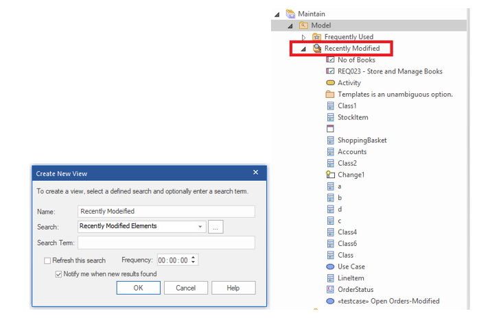
Figure 86 Recently Modified Elements
Tip #91: Create Element from Text
Select a piece of text in an application (e.g. web browser, word document, notepad++). Then drag and drop the selection to the diagram view in EA, to create an element with Name.
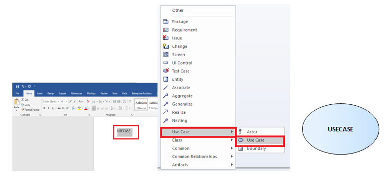
Figure 87 Create Element from Text
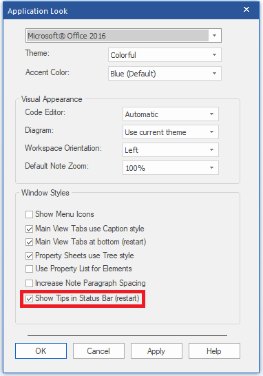
Tip #92: Enable Tool Tips
Enable tool tips in Enterprise Architect 14 using “Show Tips in Status Bar (restart) option” (Start | Visual Style).
Tip #93: Kanban Charts
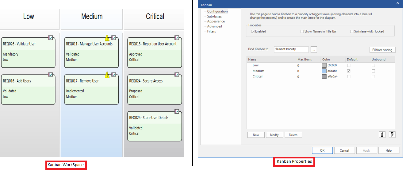
Use Kanban charts (driven by Default properties / Tagged Values) to categorize elements. To Create Kanban Charts, Right-click on diagram workspace select “Kanban” from context menu. Configure properties to categorize. Drag and drop the element in the Kanban workspace.
Tip #94: Save Server Connection
Save your server connection as an EAP file. EA icon Drop Down (Left Top)| Save as Shortcut
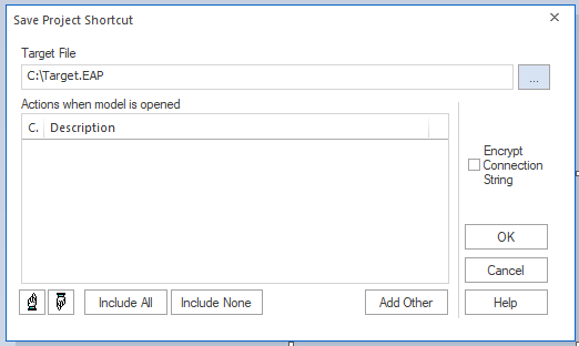
Figure 90 Save Server Connection
Tip #95: Inline Reader
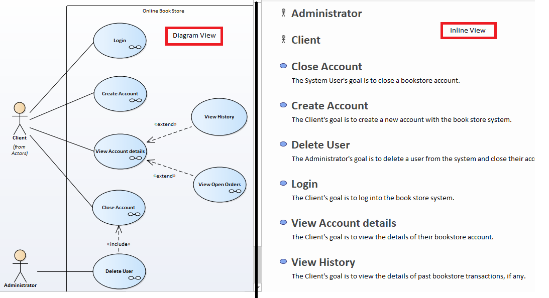
Inline Reader (Simplified version of Specification window) option represents artifact name and notes along with diagram. To access the Inline Reader, open diagram and select (Design | Diagram | View as | Toggle Inline Specification View).
Tip #96: Clone Element
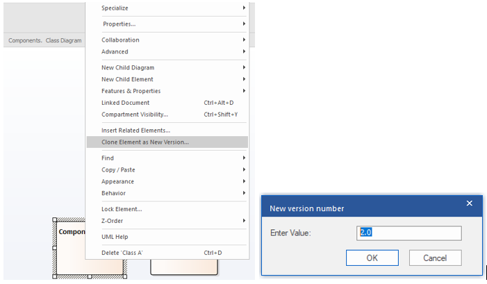
To clone the element, open the cloned diagram. Select a element Right Click on the Element | Clone Element as New Version. Enter value for version and click OK.
Tip #97: Create Charts
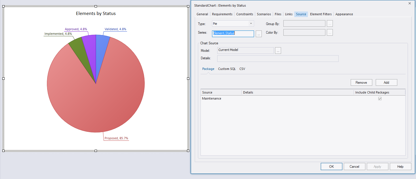
Charts in Enterprise Architect can help you manage projects, communicate strategy, identify trends and track KPI’s. Drag and drop the standard chart artifact from the tool box, double click on the artifact to open the properties. Configure Properties, type of chart. Data represented in chart can be defined from current model/external model/query/csv.
Tip #98: Save Relationship Profiles
Configure Relationship Matrix (Design | Matrix) using source/target package, element type, connector type and direction and save it as profiles (Options | Profiles | Save as New Profile) to publish in report.
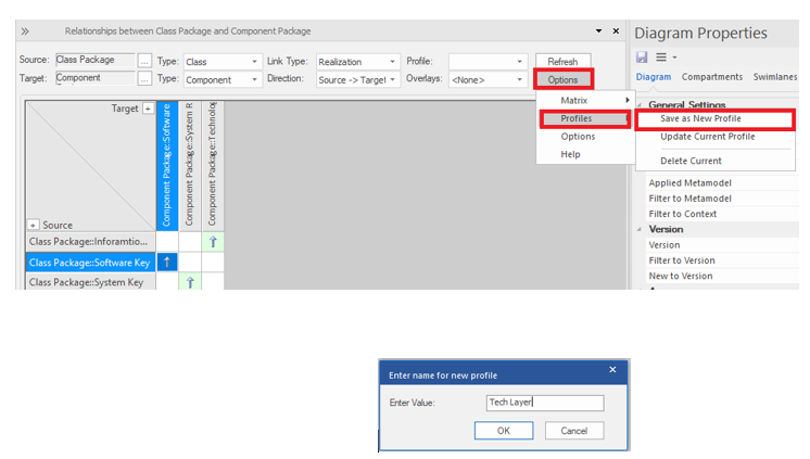
Figure 94 Save Relationship Profiles
Tip #99: Add Elements from Project Browser
In the project browser, click on “drop-down | New Element”. Use “Save” option to create multiple elements.
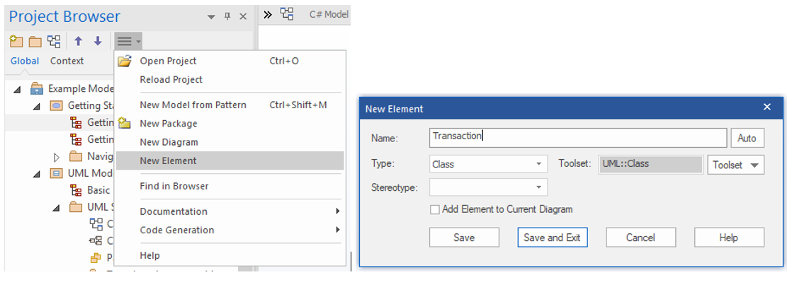
Figure 95 Add Elements from Project Browser
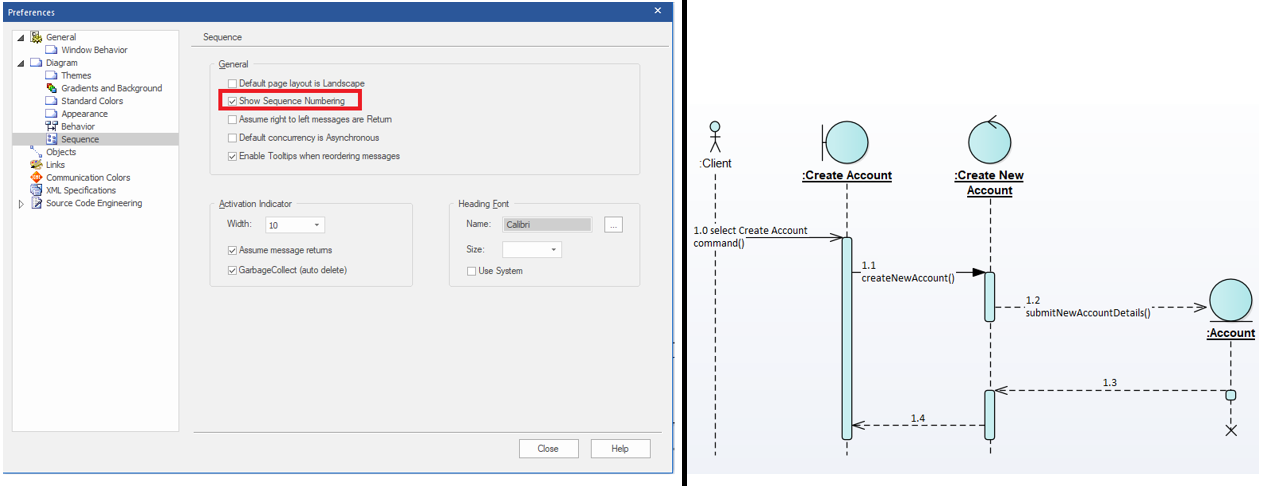
Tip #100: Sequence Numbering
Enable Show Sequence Numbering checkbox (Start | Preferences | Diagram | Sequence) to display interaction sequence between lifelines.
